Fiberglass Composite Bodywork
A Documentary and Tutorial
Shawn Mahaney
(updated 5/1/99)
 This documents
the creation of the bodywork for the University of Michigan 1998 Formula
SAE competition vehicle. It should serve as a primer for those who wish to
immerse themselves in such a task for future vehicles. Many of the
techniques described here can be improved upon and/or applied to other fibrous
composite parts, such as wing sets. It is assumed here that any bodywork
being built is mostly ornamental -- serving only limited structural requirements.
For structural applications, the author strongly encourages the use
of chassis structures with more advanced geometries such as stressed skin
monococques which may eliminate the need for much of the bodywork on a car.
Such structures have been shown to be viable as low-cost, lightweight,
easy-to-build alternatives to complex truss structures like welded tube frames.
See
http://www.sdmahaney.org/carproj/.
This documents
the creation of the bodywork for the University of Michigan 1998 Formula
SAE competition vehicle. It should serve as a primer for those who wish to
immerse themselves in such a task for future vehicles. Many of the
techniques described here can be improved upon and/or applied to other fibrous
composite parts, such as wing sets. It is assumed here that any bodywork
being built is mostly ornamental -- serving only limited structural requirements.
For structural applications, the author strongly encourages the use
of chassis structures with more advanced geometries such as stressed skin
monococques which may eliminate the need for much of the bodywork on a car.
Such structures have been shown to be viable as low-cost, lightweight,
easy-to-build alternatives to complex truss structures like welded tube frames.
See
http://www.sdmahaney.org/carproj/.
Overview
The functional objectives for race car bodywork are lightness, rigidity,
a smooth surface, control of airflow, and good looks. The constraining
factors are cost, labor time available, physical packaging, and the undeveloped
aesthetic sense endemic to engineers.
Making the panels light is a result of both the materials and process chosen,
as is the cost. Surface smoothness comes from the chosen process and the
amount of grunt labor and fussiness applied to it. Airflow and looks
have to be considered at the design stage, where packaging with other objects
needs to be worked out. Styling is best left to an *experienced* stylist.
The shape of the 1998 body, with its slab sides, harsh geometric elements,
and unnecessarily blunt nose, is all the comment I have to offer on that
point.
Fiberglass in this context is a composite material consisting of glass fibers,
mostly in the form of woven fabrics, which are saturated with an epoxy or
polyester resin that eventually hardens and gives the material shape.
Usually several plies of different weight fabrics are used to build
up the final "laminate". In portions of this body a lightweight core
material was used to separate two fiberglass skins. This geometry gives
very good specific stiffness in flexure, which was necessary in the large
flat areas of the sidepods.
A "female mold" process was chosen in order to get the best surface finish.
Using a female mold means that the outside of the final part is formed
against the mold, which should be very smooth, so the mold must be an "inverse"
of the actual part shape. Alternatively, a male mold could have been
used, but then the back side of the molded material would be exposed and
it is not necessarily smooth. With a male mold, a good deal of finishing
work (with body filler and lots of hard sanding) on the final parts is required
for a good finish.
Because it is difficult to build a female shape directly, a male "buck"
(or "plug") was built. The buck is a full-scale replica of the
final body shape. Once a smooth surface is developed on the buck, the
molds are made from the buck and then the parts are made from the
molds . In
this way the smooth surface of the buck is transferred to the molds and then
to the parts.
. In
this way the smooth surface of the buck is transferred to the molds and then
to the parts.
The final parts were also to be "vacuum bagged", a process in which atmospheric
pressure is used to squeeze the fiberglass laminate against the molds, squeezing
out excess resin into a breather cloth which is removed after the resin hardens.
This increases the ratio of glass fibers to resin which usually makes
the panels lighter with higher specific strength and specific stiffness.
For historical reference, Michigan's 1994 bodywork
was made in a male mold process, resulting in a great deal of labor in the
final weeks and fairly heavy body panels. After all that, the surface
was still not great [Of course, that car *did* WIN, so I guess it wasn't
all that bad!]. For 1995, a female mold was constructed directly without
a male buck. Working upside down, with the designer not present to
give guidance, getting the shape right and the surface smooth was not easy.
Poor mold material choices also hurt. For
1996, the body was built with an epoxy-finished male
plug, epoxy/fabric molds, and epoxy/fabric vacuum bagged parts (the male
styling buck and the various female molds can be seen lined up behind the
car). The wingset building and mounting also got thrown into our department
in '96. Altogether it was an expensive endeavor. The
1997 body consisted of a vacuum molded sheet of
thermoplastic for the nose and folded aluminum sheet on the cockpit
sides. This 1998 body was built with a process nearly identical
to the 1996 car's. A few materials were substituted to control costs.
The work generally followed these steps:
-
Material/method experimentation and practice
-
Packaging and design
-
Workspace set-up
-
Buck construction and shaping
-
Mold making
-
Part making
The remainder of this document will go through these steps, after the following
few notes
Avoid neat ideas - This isn't really a step in the process, it's
just the state of mind one needs to be in to complete a task like this the
first time, and still have their sanity. What it means is that you
should take documents like this from experienced people as carved into stone
by lightning bolts from heaven. Don't try to get inventive the first
time around - you'll cost yourself a lot more time than you'll gain.
Workspace - Enough space to house a full-scale replica of the car
(the buck), which is basically the first thing to build, is the starting
point for work area needed. Building up the buck, at least four feet
all around it is needed, *minimum*. Also needed is a flat area, at
least 4' square, for cutting dry cloth, and another flat spot a little bigger
for wetting out the cloth with resin. About 2/3 of my 2 1/2 car garage
was fine. The space will get very messy, as a project like this will
go from very dusty to very sticky and back to dusty again. The work
area should be separated from other areas and be easily cleanable. I
highly recommend a separate room with filtered exhaust ventilation. Also,
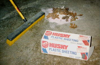
I always spread two plies of polyethylene plastic on the floor before starting.
Organization & cleaning - Having many different types of cloth,
resins, and tools around is just the first challenge in organizing. The
real trick is in keeping the dusty stuff out of the sticky stuff and the
sticky stuff off of just about everything. Sanding and grinding should
be avoided when there is wet resin exposed. To control the sticky stuff,
there should be a designated area for mixing resin and for spreading resin
on cloth pieces when that is to be done. Dedicated tools, like scissors,
should be used with wet cloth only, and cleaned regularly. Cleaning
can be summarized in three words - plastic covered, disposable, or "acetoned".
To expand -- anything sitting still that's not supposed to get epoxy
on it should be plastic covered; as many things that must touch the resin
should be disposable as possible; and the reusable things can best be cleaned
with acetone (available for about $10/gallon from hardware stores - start
with a full gallon and buy more as needed). Acetone is a mild skin
irritant and a definite neurotoxin, but boy does it get gooey resins off.
Don't drink it or bathe in it, just wet out paper towels and
wipe. It's the active ingredient on nail polish remover. It has
a strong smell and eveporates very quickly.
Clothing - These resins do not come out of fabrics, and they stick
pretty well to eyeglasses, hair, skin, and shoes. I like to keep a
junky set of clothes, including shoes and old glasses, around to change into
before working with resins. There are also some nice reusable Tyvek
suits available which zip on over clothing, though the shoes are still exposed.
On the health side, long term exposure to the resins, including
vapors, is bad. A chemical respirator is not a bad idea and good
ventilation is essential (some of the stuff stinks, too!). Disposable,
close fitting, latex gloves are essential -- expect to use several hundred.
Cutting fiberglass and sanding on the buck are good times to wear a
particulate mask.
Avoiding "neat ideas" II - This is a simple mantra that
must be repeated over and over again until you believe it - "AVOID NEAT IDEAS".
Little things that look like ways to save tons of work sound too good
to be true, and they usually [and I mean almost always] are. This advice
came from the guys at Gougeon Brothers, and they were right. It took
me three years of doing this sort of work before I had a single idea that
actually saved me work. Trust us - you are not the first person to
make fiberglass bodywork, so whatever your idea is, we probably already tried
it and spent the next week redoing something because of it. One more
time, "AVOID NEAT IDEAS'. [One remotely possible exception here is
in the building of custom tools and jigs. Given some serious thought,
you just might be able to make a good mixing stick or sanding pad. Still,
don't push it.]
Do the hard work early - The way this method works, one is working
with progressively harder and more difficult to sand materials. It
is always more difficult to correct things "tomorrow". In corollary,
complete fussiness at every stage is always rewarded by making the next step
easier.
On with the actual project...
Material/Method Experimentation and Practice
A test shape was made with which to make a trial mold and part. An
attempt was made to have compound curves, linear curves, sharp creases and
flat surfaces intermixed on the part surface. This would allow a good
overview of how the final part would reflect light as well as allowing some
practice with the various materials. I highly recommend doing a small
tabletop part like this first.
The shape was carved roughly out of a piece of two inch polystyrene foam
(pink insulation) and epoxy bonded to a sheet of
plywood . With
the foam carved as close to final shape as possible, the foam and board were
covered with a thin coat of West System epoxy filled with very little colloidal
silica. The epoxy layer is meant to put a hard shell on the foam and
the silica makes it a bit tougher. This coat was applied with a thin
foam roller. The rollers are sold by Gougeon Brothers (GB) and are
often cut in half or into thirds to make a shorter roller.
. With
the foam carved as close to final shape as possible, the foam and board were
covered with a thin coat of West System epoxy filled with very little colloidal
silica. The epoxy layer is meant to put a hard shell on the foam and
the silica makes it a bit tougher. This coat was applied with a thin
foam roller. The rollers are sold by Gougeon Brothers (GB) and are
often cut in half or into thirds to make a shorter roller.
After the sealing coat cured hard, the first coat of thick filled epoxy was
applied with a notched spreader. The epoxy was West System filled very
heavily with microlight filler (GB #410). This filler is added to the
point where the resin COMPLETELY LOSES ALL FLUIDITY. This will require
mixing in as much filler as you think the resin can possibly make sticky,
and then adding just as much again. [Special Tool #1 - a good solid
mixing stick is indispensable for mixing the thick filled resin. I
took a 10" length of 1" dowel rod and tapered one end to a round blade. I
got this idea after visiting GB and seeing someone else's mixer hanging up
with "Thixcalibur II" on the "hilt"] The filler makes the epoxy take
up a lot more volume and be very easy to sand.
The rectangular notched spreader is provided by GB and has triangular notches
on three sides, each side a different depth. The deepest notches are
used first. Once this very bumpy surface cures, it can be sanded down
very quickly to level out the surface. High spots will sand down until
the base sealer coat is exposed, then the whole surface should be covered
with filled epoxy to fill in the first set of notches. After a little
sanding, a new notched layer can be spread using the next smaller set of
notches. For
the test part, the round end of a GB mixing stick (much like a popsicle stick)
was used to fillet the base of the part into the plywood. A sharp inside
corner here would make it very difficult to remove the mold.
For
the test part, the round end of a GB mixing stick (much like a popsicle stick)
was used to fillet the base of the part into the plywood. A sharp inside
corner here would make it very difficult to remove the mold.
With the surface fully developed in filled epoxy, another sealer coat of
epoxy was rolled onto the pattern surface. Keeping small bubbles out
of the epoxy is very difficult. It can help to drag the foam roller
over the surface after rolling out the coat. This final epoxy coat
was then wet sanded with increasing grits up to 600. Getting the pattern
surface perfect really pays off - going up to 1500 grit paper or even polishing
compounds is not unreasonable for a pattern that is going to be used for
even limited production.
The pattern surface was cleaned and waxed with plain paste car wax (I like
Turtle Wax). Several thin coats of wax are needed for a good release.
Big glops or extreme swirls should be avoided as these may show up
in the mold surface. After the wax is very dry (*not buffed out!*),
the mold is laid up on the pattern. More details will come in the
description of the full-size molds.
After several layers of mold material were laid on the pattern, starting
with a plain resin "gel coat", the mold was pulled off and cleaned. The
test part is laid up in the mold similarly, starting with a gel coat and
progressing through several layers of fiberglass cloth. The part molded
under pressure in a vacuum bag to push air bubbles and excess resin out.
Packaging and Design
"Design" work consisted of taking very specific criteria from the team groups
and fitting the body around the
frame as
designed. The engine team desired sidepods for radiator cooling air,
so the side pods are simply as large as possible without rubbing on the ground
or extending past the tires. A couple nose designs were presented to
the team - the
loser
as
designed. The engine team desired sidepods for radiator cooling air,
so the side pods are simply as large as possible without rubbing on the ground
or extending past the tires. A couple nose designs were presented to
the team - the
loser is shown
here.
is shown
here.
Simple 2-D sketches were used to determine fit and generate basic dimensions
which would be used in building the buck. A few cross sections could
be taken and recreated in plywood to be used a templates in the buck - this
was possible only because the sidepods were simple and straight - two
cross-sections defined their front view profile pretty well. More complex
shapes would required a 3-D physical or CAD model to get accurate cross sections
to use in building a foam buck.
Workspace Set-up
After thorough cleaning, every horizontal surface of the garage was covered
in heavy plastic sheet, including the entire floor and all the work tables.
It is not sufficient to cover an area a few feet out from where the
buck will be -- the entire floor must be covered or there will be dots of
resin to scrape off later (consider what happens when someone walks off the
plastic covered area with wet epoxy still on the bottoms of their shoe).
I used duct tape continuously around the edge, drawing the sheet as
tight as possible. The plastic will last better and let things roll
more easily if it is kept
flat.

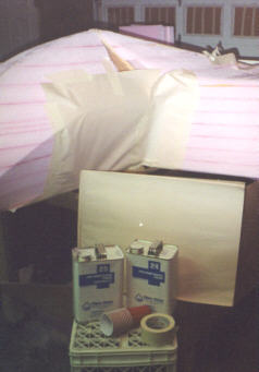
Keeping resins, cleaners, sanding tools, and other items separate and organized
has always been a challenge in body building. Having a number of free
shelves available was wonderful. Here the various resins are on a rolling
shelf unit , while buck building supplies, cleaning items, and mixing supplies
are on other
shelves.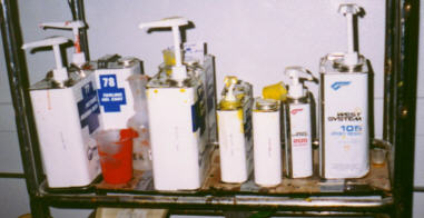

Buck Construction and Shaping
A rolling cart was constructed for the buck on 2" casters. Having the
buck easily movable like this has been a great convinience everywhere I've
seen it done. It is important that the cart be a comfortable height
for working on all surfaces. If there is significant area to be worked
on the underside, as under the sidepods of this shape, the buck should not
be so low that it is difficult to work underneath. A small step stool
was helpful in getting at the very top of the buck. Two inch casters
were passable on the smooth parts of the floor, but I wish I'd have used
larger ones to get over small cracks.
An exact copy of the frame was made out of 1" plywood (actually two 1/2 inch
particle board sheets screwed and glued together to emulate the 1" square
bars in the floor plane and mid plane) and 1" dowel rods. The front
roll hoop was represented by a piece of the 1" plywood cut to rough shape
with a jig saw and then rounded with a 1/2" radius rounding-over router bit.
The floor plane was not quite flat, the foot box end being 1" higher
than the rear of the floor pan, so the front and rear sections of it were
hinged with a couple pieces of sheet aluminum. With the floor plane
in position on the floor, the mid plane was suspended above it at the appropriate
height. The dowel rods were cut to length and mitered, being measured
by holding them up to the real steel frame, and positioned between the mid
and floor planes using liberal amounts of hot-melt glue. The hot-melt
glue is remarkably strong, but where there were very large gaps fiberglass
cloth was wadded into the joint to reinforce it. The members above
the mid plane were added similarly, with care being take to orient the roll
hoop properly. To my surprise, the pseudo-frame was self-supporting
and even could be handled quite a bit with just the hot-melt glue holding
it together.
Some provision must be made for securing the buck to the cart in such a way
that it can be quickly removed. Knocking the buck off the cart could
be catastrophic! [Yes, I have had to repair damage from such an
incident...] A hole was drilled through both the floor plane and the
platform on top of the cart. A large lag bolt was passed up through
the cart platform, secured to the platform with a nut and washer and then
the actual buck could be held down onto the bolt with another nut.
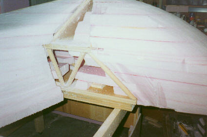

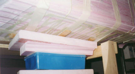
The "meat" of the buck was rigid polystyrene insulating foam. 4x8'
sheets were bought in various thicknesses, mostly 2". 4" thick sheets
can be found and make building up the shape that much faster. Pieces
were rough cut with a coarse hand saw and glued onto the buck with caulk-gun
construction adhesive. Temporary securing can be done with duct tape
pretty well. It is best to not have construction adhesive between sheets
in areas that will later be cut or sanded. The adhesive terribly slows
down the hot wire cutter and simply does not sand - it pulls out in strips
often taking lots of foam with it.
 The hot wire
cutter is a simple but very effective tool for rough shaping the foam. I
built one out of 1x2" hardwood, a couple 3" steel pulleys, and a small turnbuckle
for each end of the wire. NiCr wire is recommended and wire can be
bought specifically for this purpose. The wire will stretch when hot,
so some mechanism must be provided for maintaining tension when the wire
is hot and relieving it when the wire is cold. A 10 amp 12V battery
charger is sufficient for a cutter like this. I built this one to give
me a very long cutting wire, over 5', but it could have had more depth as
this only gave me about 2'.
The hot wire
cutter is a simple but very effective tool for rough shaping the foam. I
built one out of 1x2" hardwood, a couple 3" steel pulleys, and a small turnbuckle
for each end of the wire. NiCr wire is recommended and wire can be
bought specifically for this purpose. The wire will stretch when hot,
so some mechanism must be provided for maintaining tension when the wire
is hot and relieving it when the wire is cold. A 10 amp 12V battery
charger is sufficient for a cutter like this. I built this one to give
me a very long cutting wire, over 5', but it could have had more depth as
this only gave me about 2'.
The wood cross sections in the side pods allowed the wire cutter to be pushed
in until contact was made with both boards and then it was dragged along
them, providing a very close approximation of the final shape.
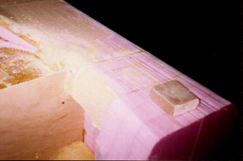
A single 1/4" plywood template was used for the profile of the nose. Two
pieces of differently colored foam were glued to it to represent the front
of the crush zone. Cutting down the foam on the nose, I would know
I went too far if I found the colored foam.

Further shaping is done with wood shaping tools (e.g. Stanley ShurForm),
knives, hand saws, and coarse sandpaper.
Tedious, careful measurements are needed to keep symmetry left and right,
especially on the face of these side pods. The rim of the sidepod opening
was sketched out with dividers to a uniform width. The center of the
sidepod was hogged out to about 3 inches depth, thought more depth would
have been helpful in later mold building and part making.
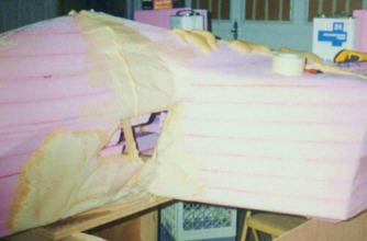
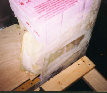
Large open areas and smaller gaps can be filled with expanding 2-part foam.
Crude molds of paper and masking tape were used to fill in several
sections around the nose and in the rear. Paper like the newsprint
used here may stick to the foam and require a little effort to shave off.
Plastic sheets might work but sometimes the foam gets hot enough while
hardening to melt through. This is the first step where the disposable
gloves are indispensable -- the two-part foam is based on the same stuff
as Super Glue and will stick to skin and fingernails like nothing else.
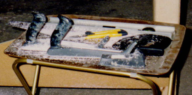
[Special tools #2-9: custom foam sanding blocks. Pictured here is my
most used sanding tool, a piece of 1 1/2" foam about 3" by 4" with one edge
rounded into a bull nose, with coarse sandpaper glued to it with spray adhesive
(3M Super77). These were made in many shapes and sizes with various
grits glued to them. The paper usually peels off pretty cleanly and
more can be glued on to the same foam block]
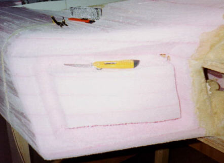
Since the bottom of the sidepods could be approximated with a flat plane,
panes of glass were cut and glued to the shaped foam. This would save
a lot of work in later finishing, since the bottom would already be perfectly
smooth. Inexperience in working with glass compounded the difficult task
of gluing to *underside*. One side broke into three pieces, creating
enough joint smoothing work to nearly negate the benefits of the glass surface.
After the foam was shaped as close to perfect as possible, the buildup of
filled epoxy sanding compound began. After laying on a very very thick
(completely non-fluid) layer with the notched spreaders, sanding could begin
using all sorts of store bought and custom tools. Mixing the compound
here involves a small amount of West System epoxy and large quantities of
#410 Microlight filler. Again, one should mix as much filler into the
epoxy as one thinks can possibly be wetted by the epoxy, then add that
much again. It is important for the first layers of filler that they
stand up completely on their own. The notched layer of filled epoxy
will go on better and be more usable in sanding and shaping if the notched
trails all run in the same direction. Custom sanding tools here included
blocks of foam with 60 or 100 grit sandpaper glued on (3M Super 77 works
well and lets the paper be peeled off later). I liked to put a cylindrical
profile on one side of the sanding block. For large smooth areas a
thin sheet of Plexi-Glas with sandpaper glued to one side and any sort of
handle on the back works well.
Several alternating notched and smooth layers of sanding compound will build
up the surface to the desired shape with no low spots. This process
will consume and alarming amount of filler and epoxy. In all I went
through 2.5 $20 cans of Microlight filler, almost 80% of that in the first
notched/smooth layers.
Moldmaking
Once the buck surface is at the desired shape, it should be dry sanded
with smoother grits up to 150 or 200. Then, for a hard
topcoat , a
layer of unmodified epoxy is rolled on. Small bubbles should be avoided
in this layer as much as possible. One helpful technique is to drag
a very thin knapp or foam roller along the epoxy in slow even stripes.
, a
layer of unmodified epoxy is rolled on. Small bubbles should be avoided
in this layer as much as possible. One helpful technique is to drag
a very thin knapp or foam roller along the epoxy in slow even stripes.
When this layer is cured to full hardness, the really tough sanding begins.
Wet sanding with progressively finer grits up to 600 or more is essential
for a good mold release. Some people recommend working up to rubbing
and polishing compounds. For production molds this level of smoothness
would pay off. I quit after the 600 grit.
Now that the surface was nice and smooth, I dulled it again with several
coats of wax. Paste car wax works well enough, but there are commercial
mold releases that might work better. Note that heavy
 swirl patterns
in the paste may come through in the mold and the final parts. I tried
a spray-on release from FibreGlast for a couple parts with usable results.
swirl patterns
in the paste may come through in the mold and the final parts. I tried
a spray-on release from FibreGlast for a couple parts with usable results.
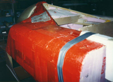
Once the wax was very dry on the surface, the first layers of the mold were
ready to go on. The first layer was a "gel coat", a layer of pure resin.
For the molds I used polyester resins which are usually significantly
cheaper than epoxy resins. FiberGlast sells a polyester resin specifically
for mold gel coats -- that's the red stuff in these pictures. This
resin costs a little bit more than the regular molding resin but is
supposed to be a little harder and scratch resistant. The opacity from
the red color also helps one judge surface quality better.
Polyester resins thicken up pretty fast, and they stink very badly. One
must work with small batches of resin and have good ventilation [a chemical
fume mask is recommended]. Because the polyester resin sets up quickly
and is difficult to clean up even when liquid, the application tools must
be considered disposable. Bulk quantities of wood handled brushes and/or
small foam rollers are good things to buy early on.
With the gel coat hard (or even still a little tacky) the first layers of
cloth for the mold structure can go on. I used the 1.4
oz/yd2 for the very first layer. The strongest structures
will come from continuous sheets of glass cloth hand fitted and stretched
over the buck surface, but it is much more convenient to work with smaller
pieces of cloth, especially around tight
curves. With
the resin hardening in 20 minutes or less, it was important to work fast,
so I pre-cut the strips and patches of cloth I thought I would need. This
also keeps the cutting area clean since I wouldn't come back to it with my
gloves covered in resin. Separate from the cutting area is the wet-out
area where cloth is wetted with resin before being laid on the buck.
With
the resin hardening in 20 minutes or less, it was important to work fast,
so I pre-cut the strips and patches of cloth I thought I would need. This
also keeps the cutting area clean since I wouldn't come back to it with my
gloves covered in resin. Separate from the cutting area is the wet-out
area where cloth is wetted with resin before being laid on the buck.
Along the sharp edges of the nose and around all the free edges 1-3" wide
strips of 1.4 oz. cloth were laid first. It is only the tackiness of
the polyester resin that will keep the cloth wrapped around the sharp curves
so the lightweight cloth is necessary for outside corners and curves. With
cloth this light and with a good gel coat, pre-wetting the cloth is not
necessary. Resin can be brushed onto the cloth in-place. This
is especially helpful as a work speed-up when working with the fast curing
polyester resin.
[Special tool #10 - Polyethylene milk jugs worked out very well as polyester
resin pots. A large window was cut out for access to the resin while
the handle part was left connected. Being polyethylene, the resin will
peel out and the jug can be reused

After the edges and curvy parts had strips of cloth on them, patches of cloth
were tiled onto the rest of the surface.
Care should be taken when putting the first layers of cloth on top of the
gel coat. Once the resin becomes tacky, it will be easy to rip up parts
of the gel-coat when adjusting the cloth. The nose mold gel coat was
damaged in this way.

After the first layer of 1.4 oz cloth was laid on, another layer went on
along with multiple layers of reinforcing strips around the edges and along
the tight curves where the first strips had gone. The 1.4 oz layers
were backed by a 3 oz layer and a 6oz layer. After the first two or
three layers of cloth were on, the molds were released from the buck. The
initial release is much easier when the panels are still somewhat flexible.
At this point I regretted trying to wrap the panels tightly around
some of the bars. Layup and release are much easier with at least two
inches of extra flat space on the buck beyond the end of the final part.
To make these parts release without badly damaging the edge of the
molds, I had to run around the edges with a knife, trimming the layup very
close to the final part edge, and then prying up very carefully. Initial
mold or part release always takes some grunt effort and a lot of force.
Some edges of the mold were damaged in this process. Long thin
shims are useful in releasing parts, but again caution must be exercised
or the mold surface can be damaged. To release the mold for the nose,
which hugs a shape that ends with no draft, I cut the bottom of the mold
in half and then spread it apart. Also useful are things to grab onto
on the outsides of the molds. Bonded on or laid in strips of glass
tape will work here.
Then a layer of thick chopped strand mat (approx. 13.5 oz/yd2)
was added to all the flat or gently curving areas. The mat will absorb
a tremendous lot of resin so be ready.

The broad flat areas were stiffened up by bonding pieces of corrugated cardboard
and a top layer of 6oz cloth to them to make a cored structure.
The open ends of the sidepods would be very floppy if not reinforced so a
frame was bonded on to either end using either foam core boards or leftover
dowel rod and glass tape. The heat sensitivity of the epoxy resin was
taken advantage of here by using a hair dryer to speed the cure of one
side.

Partmaking
Vacuum bagging was not done in making the molds. The polyester resin
cured too fast to set up a vacuum bag and controlling the fiber/resin ratio
was not important. The final parts were vacuum bagged so a few extra
things were done to prep the molds for vacuum bagging.
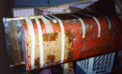
The outside of the molds had many little bits of glass fiber protruding which
could poke holes in the vacuum bag. Scraps of breather cloth and release
fabric were taped and/or glued to the outsides of the molds to cover these
tips. The edges of the mold were also very rough and had a near knife-edge,
so masking tape was folded over these edges. Many edges of the mold
had been trimmed or laid up only to the very edge of the part, leaving no
extra space. In particular, some sides of the sidepod inlets were not
very deep and not enough material was there for later riveting of the screens
into the final part. These short edges were "extended" using folded
over masking tape. The edges of the tape will be visible in the final
part, so be neat if the line is not going to be trimmed off later.

The nose was the first piece to be made in the vacuum bag. The initial
lay-up is just like making the molds. The mold was cleaned, any small
defects filled with glazing putty, and the surface was waxed. An epoxy
gel coat was painted into the mold with FibreGlast System 2000 epoxy and
some yellow tinting they sold me. The System 2000 had a very hard time
setting up an even coat on the wax -- it fish-eyed terribly. This is
something one would have to work out with FibreGlast, or go back to West
System epoxy which has shown much better behavior over wax mold release.
Once a solid gel-coat was finally achieved (after 3-coats, which ruined
the effect of the tint as the colors did not match perfectly and the fish-eye
pattern came through), the first layers of glass went on. Super-fine
0.73 oz/yd2 cloth was used at first, but was found entirely too
fine to work with and 1.4 oz was used for the actual first layers. Working
with small pieces of glass, care was taken to get all air out from under
the wet cloth. A single layer of 1.4 oz cloth is not strong enough
to not tear when the vacuum bagging release cloth is released, so a layer
of 3 oz cloth was put on immediately after the 1.4. The yellow tint
was used with the epoxy in both of these layers.
On top of the wet glass goes a release fabric which is not supposed to stick
to the epoxy and behind that goes the breather cloth. The breather
is a very open airy material (loose felt) that lets air move under the plastic
to the vacuum pump and also soaks up the excess resin which is being squeezed
out of the lay-up.
The resin must still be liquid before the vacuum is applied to get the benefits
of bagging, so time must be conserved in doing this work. All the cloth
pieces were pre-cut and the vacuum bag was ready to go before any resin was
mixed. Two-hour pot life resin was used and temperatures were as cool
as possible while working. The fastest way to get a lay-up sealed in
a vacuum bag is to start with an actual "bag", which is usually a large sheet
of 2 mil plastic folded in half and sealed on two of the three open sides
using duct putty or the expensive tacky-tape that is sold for this purpose.
With this bag pre-made, the mold can be slipped in after lay-up, the
vacuum hose stuffed in, and then the open end can be gathered up and sealed
around the hose with a zip tie. There will be some leakage around the
hose and zip-tie end, so this must be taken up with a bigger pump.

It can be difficult to get a good seal between two sheets of plastic. I
never got a great seal on the very large (2 10'X25' rolls) bag I made, partly
due to one of the sheets being covered in some kind of dust when I got it.
Some other alternatives for premade bags exist in large trash bags
for smaller parts, or bags from shipping supply companies that are used to
bag pallets full of merchandise. Given a problem bag, and that the
problem is not found until there's a laid up part waiting for the bag, the
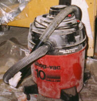
only fast solution is a very big vacuum pump. A shop vac like
this can move a lot of air, but can only maintain a couple inches of vacuum.
This is still better than a no-pressure lay-up.
As with the molds from the buck, the parts were released after just a couple
layers of cloth were laid up. After reinserting the parts, another
layer of 3 oz cloth was vacuum bagged in along with many reinforcing strips
in corners or high-wear areas (like the tip of the nose and the outside corners
of the sidepods). Extra reinforcement was also added where there were
likely to be fasteners.

To give the nose more stiffness, a rib of two plies of Aeromat was bonded
in and backed up with 3 oz glass to make a small core/skin structure.

The sidepods were made similarly, but with an extreme amount of reinforcing
layers in the front edges of the intake and a nearly full layer of Aeromat
and 3 oz cloth to give the flat sections stiffness.

The rough edges were trimmed with a Dremel using a reinforced cutting disc
(not the usual flat plain discs that come in packs of 100, but the thicker
discs with reinforcing fibers).

After drilling holes for pop rivets, the screens (two plies of normal aluminum
window screen) were riveted in and the panels were delivered for painting.
